Time Counter Using Digital Logic Gate
Components required:-
2.Flip Flops
3.AND logic gate
4.Power Supply
Now we will discus about each components given above step by step manner to understand the working behaviour of timer digital circuits at very basic level.
1.Proteus Software: This software is used for desigining of digital circuit and their simulation purpose
above given video is designed in proteus .You can download the proteus from this link .After downloading the proteus you will get the interface like this .
you can go through this video to understand how to work on the proteus software .In this video you will
get the idea about the functionality of each and every icon shown in the image
2.Flip Flops:-A circuit that has two stable states is treated as a flip flop. These stable states are used to store binary data that can be changed by applying varying inputs. The flip flops are the fundamental building blocks of the digital system. Flip flops and latches are examples of data storage elements. In the sequential logical circuit, the flip flop is the basic storage element. The latches and flip flops are the basic storage elements but different in working. There are the following types of flip flops:
a. SR flip flop
b. JK flip flop
c. T flip flop
d. D flip flop
From above types of flip flop we have used only JK type flip flop . Now we will understand the working of JK type flip flop .
b.JK flip flop:
The JK flip flop is used to remove the drawback of the S-R flip flop, i.e., undefined states. The JK flip flop is formed by doing modification in the SR flip flop. The S-R flip flop is improved in order to construct the J-K flip flop. When S and R input is set to true, the SR flip flop gives an inaccurate result. But in the case of JK flip flop, it gives the correct output. .
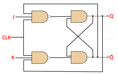
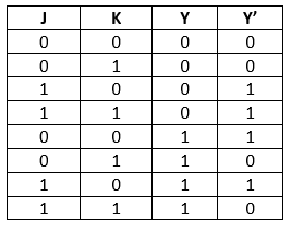
In J-K flip flop, if both of its inputs are different, the value of J at the next clock edge is taken by the output Y. If both of its input is low, then no change occurs, and if high at the clock edge, then from one state to the other, the output will be toggled. The JK Flip Flop is a Set or Reset Flip flop in the digital system.
Truth Table:
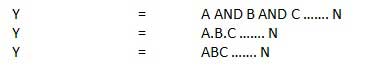
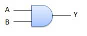
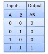
3.AND logic gate:-A circuit which performs an AND operation is shown in figure. It has n input (n >= 2) and one output.
Logic diagram
Truth Table
4.Power Supply:-In we use two types of power supply one is dc voltage battery of 9v and other is digital pulse voltage .For this we use 555 timer circuit which will create digital pulse voltage
From the output pin of 555 timer we will get the digital pulse of required time period.


No comments:
Post a Comment