Saturday, February 25, 2023

Mobile Sensor fusion with MATLAB


In this project we will learn how to transfer our realtime mobile sensor data to our desktop ,now we apply algorithm on these sensor data to get some meaningful result,This whole procedure we have divided into three steps.
  1.Setup required in desktop
  2.Setup required in mobile
  3.Algorithm 

1. Setup required in desktop:-On the desktop open the MATLAB command window and type there first command (connector on <password>) 

after hitting the enter we get the DNS name or the IP address of the desktop  . Now we will use this IP address  in further setup in mobile application 
 
2.Setup required in mobile:-Download the MATLAB app from the given link .After installing the app you get the the interface like this


 click on the link "Connect to Your Computer" after that you will we redirect to this interface 


  At top right end  click on "Add a Computer"  after that you will get the interface given below now here put the computer IP address ( port :-31415 -by default) password will same as you have set in first heading after filling all this click on the link top right("Connect")


After clicking the connect come to the desktop . Further procedure is explained under the third heading 
  
3.Algorithms:-In the Command Window, create a mobiledev object in MATLAB; for example: 
 
m = 
mobiledev with properties:

                   Connected: 1
           Available Cameras: {'back' 'front'}
                     Logging: 0
            InitialTimestamp: ''

   AccelerationSensorEnabled: 0
AngularVelocitySensorEnabled: 0
       MagneticSensorEnabled: 0
    OrientationSensorEnabled: 0
       PositionSensorEnabled: 0 


The displayed output should show 

 Connected: 1

indicating that the mobiledev object has successfully established a connection to the app.

Prepare for Data Acquisition

Enable the acceleration sensor on the device.

m.AccelerationSensorEnabled = 1;

Start Acquiring Data 

After enabling the sensor, the Sensors screen of MATLAB Mobile will show the current data measured by the sensor. The Logging property allows you to begin sending sensor data to mobiledev
  
m.Logging = 1; 

The device is now transmitting sensor data.

During logging, the device is held or kept in a pocket while walking around. This generates changes in acceleration across all three axes, regardless of device orientation. 

Retrieve Logged Data

accellog is used to retrieve the XYZ acceleration data and timestamps transmitted from the device to mobiledev

[a,t] = accellog(m); 

Plot Raw Sensor Data 

The logged acceleration data for all three axes can be plotted together. 

plot(t,a);
legend('X', 'Y', 'Z');
xlabel('Relative time (s)');
ylabel('Acceleration (m/s^2)'); 


Process Raw Acceleration Data 

To convert the XYZ acceleration vectors at each point in time into scalar values, the magnitude is calculated. This allows large changes in overall acceleration, such as steps taken while walking, to be detected regardless of device orientation. 
x = a(:,1);
y = a(:,2);
z = a(:,3);
mag = sqrt(sum(x.^2 + y.^2 + z.^2, 2)); 

The magnitude is plotted to visualize the general changes in acceleration. 
plot(t,mag);
xlabel('Time (s)');
ylabel('Acceleration (m/s^2)'); 


The plot shows that the acceleration magnitude is not zero-mean. Subtracting the mean from the data will remove any constant effects, such as gravity. 


magNoG = mag - mean(mag);

plot(t,magNoG);
xlabel('Time (s)');
ylabel('Acceleration (m/s^2)'); 

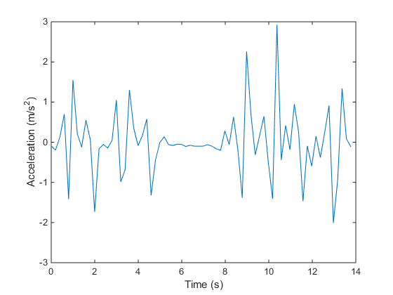
The plotted data is now centered about zero, and clearly shows peaks in acceleration magnitude. Each peak corresponds to a step being taken while walking.

Count the Number of Steps Taken

findpeaks is a function from Signal Processing Toolbox that is used to find the local maxima of the acceleration magnitude data. Only peaks with a minimum height above one standard deviation are treated as a step. This threshold should be tuned experimentally to match a person's level of movement while walking, hardness of floor surfaces, etc.

minPeakHeight = std(magNoG);

[pks,locs] = findpeaks(magNoG,'MINPEAKHEIGHT',minPeakHeight);

The number of steps taken is simply the number of peaks found.

numSteps = numel(pks)

The peak locations can be visualized with the acceleration magnitude data.

hold on;
plot(t(locs), pks, 'r', 'Marker', 'v', 'LineStyle', 'none');
title('Counting Steps');
xlabel('Time (s)');
ylabel('Acceleration Magnitude, No Gravity (m/s^2)');
hold off;

Clean Up

Turn off the acceleration sensor and clear mobiledev.

m.AccelerationSensorEnabled = 0;

clear m;


Monday, January 9, 2023

Electronics Project (Time Counter)

                          Time Counter Using Digital Logic Gate  


Components required:- 

2.Flip Flops 
3.AND logic gate 
4.Power Supply 

Now we will discus about each components given above step by step manner to understand the working behaviour of timer digital circuits at very basic level.   
 

1.Proteus Software: This software is used for desigining of digital circuit and their simulation purpose

                                above given video is designed in proteus .You can download the proteus from this link .After downloading the proteus you will get the interface like this . 


you can go through this video to understand how to work on the proteus software .In this video you will

get the idea about the functionality of each and every icon shown in the image  

2.Flip Flops:-A circuit that has two stable states is treated as a flip flop. These stable states are used to store binary data that can be changed by applying varying inputs. The flip flops are the fundamental building blocks of the digital system. Flip flops and latches are examples of data storage elements. In the sequential logical circuit, the flip flop is the basic storage element. The latches and flip flops are the basic storage elements but different in working. There are the following types of flip flops: 
   a. SR flip flop 
   b. JK flip flop 
   c. T flip flop 
   d. D flip flop 

From above types of flip flop we have used only JK type flip flop . Now we will understand the working of JK type flip flop  .

b.JK flip flop:

The JK flip flop is used to remove the drawback of the S-R flip flop, i.e., undefined states. The JK flip flop is formed by doing modification in the SR flip flop. The S-R flip flop is improved in order to construct the J-K flip flop. When S and R input is set to true, the SR flip flop gives an inaccurate result. But in the case of JK flip flop, it gives the correct output.

.

Basics of Flip Flop

In J-K flip flop, if both of its inputs are different, the value of J at the next clock edge is taken by the output Y. If both of its input is low, then no change occurs, and if high at the clock edge, then from one state to the other, the output will be toggled. The JK Flip Flop is a Set or Reset Flip flop in the digital system.

Truth Table:

Basics of Flip Flop 

3.AND logic gate:-A circuit which performs an AND operation is shown in figure. It has n input (n >= 2) and one output.
AND gate

Logic diagram

AND Logical Diagram

Truth Table

AND Truth Table

4.Power Supply:-In we use two types of power supply one is dc voltage battery of 9v and other is digital pulse voltage .For this we use 555 timer circuit which will create digital pulse voltage  


From the output pin of 555 timer  we will get the digital pulse of required time period. 


Monday, February 28, 2022

Robotic Hand(arm) and its working

                                             ROBOTIC ARM DESIGN

fig1.1:    6-AXIS ROBOTIC ARM 


  • INTRODUCTION& PROJECT FORMULATION  
  • PROJECT DESIGN 
  • DEVELOPMENT AND IMPLEMENTATION 
  • CONCLUSION AND SCOPE            
                            
now we will try to understand every part one by one so let's start
  

                                  INTRODUCTION AND PROJECT FORMULATION


1.1 Overview   

 A robotic arm is a type of mechanical arm, usually programmable, with similar functions to a human arm; the arm may be the sum total of the mechanism or may be part of a more complex robot. 

   The links of such a manipulator are connected by joints allowing either rotational motion (such as in an articulated robot) or translational (linear) displacement. The links of the manipulator can be considered to form a kinematic chain. The terminus of the kinematic chain of the manipulator is called the end effector and it is analogous to the human hand. 

1.2 Some types of Robot in market  
    
cartesian robotic arm
 
fig 1.1: Cartesian robotic arm
 
 
SCARA robot
 
fig1.2:SCARA Robot
Articulated arm
fig 1.3: Articulated arm


1.3: Applications  

Robotic arms are typically used for industrial applications. The application is the type of work robot is designed to do. Different applications will have different requirements. 

 For example, a painting robot will require a small payload but a large movement range. On the other hand, an assembly robot will have a small workspace but will be very precise and fast. Industrial robots are designed for specific applications and based on their function will have their own movement, linkage dimension, control law, software and accessory packages. Below are some types of applications: 

• Welding Robot  

• Material Handling Robot  

• Palletizing Robot  

• Painting robot 

• Assembly Robot  

• Space borne applications 

• Pick and place  

• Drilling  

1.4 ADVANTAGES AND DISADVANTAGES  

Advantages: 

• Low Cost         

• Helpful for disabled person              

• Has 6 degrees of freedom 

 • Can be easily controlled by your mobile phone  

Disadvantages :  

• Complex circuitry 

• Requires an app for functioning  

• May affect the human jobs


                                    2:  PROJECT DESIGN 

It is the second part of our project design in this part we will try to understand backend mechanism of robotic arm and its control diagram

 2.1 Basic block diagram

 
fig 2.1 Basic block diagram


2.2  Robotic Arm  Assembly: 

It will be consisting of a 3D printed robotic arm with servo motors for its motion. We will be using 6 servo motors one for the base rotation , one will be ensuring the up/down movement of shoulder , one for movement of elbow joint and the last one will be used for the gripping action of the arm

2.3 Circuit Design: 


fig 2.1: Circuit design 


• This Circuit is responsible for the working of the project.  
• Digital pins 7,8,9,10,11,12 is used up by the servo motors and 13(TX) and Analog pin A0(RX) for serial communication.  
• We connect the components as shown in the circuit diagram.  
• Servo motor usage, S1 -> Waist, S2-> Shoulder, S3-> Elbow, S4-> Wrist Roll S5-> Wrist Pitch, S6-> Grip. These servo motors are used to drive the robotic arm  
   

                      3 : Development and implementation


3.1: Flow Control  

fig 3.1:Block diagram to control arm 

• Initially The signal is sent by the mobile via Bluetooth. 
• Signal is received by the microcontroller and it computes accordingly which component is to be controlled.
 

3.2 Programming    


3.3.2 Explanation of the program  

• #include is used to operate the servo using servo related functions. 
• Servos are initialized to the pin as, S1 to 12, S2 to 11, S3 to 10, S4 to 9, S5 to 8 and S6 to 7 .  
• Also we have initialized the initial positions of the servos in the variables servo1Pos, servo2Pos, servo3Pos, servo4Pos, servo5Pos, servo6Pos. 
• In void setup() we have set the baudrate to 9600 for serial communication with object  
• In void loop(), we write the initial positions of the servos. 
• if(serial. Available()>0) is used to reject the garbage values <0. 
• We have set some constraints for the ‘pos’ variables in the if loop because of some mechanical limitations of the arm. These values were found by trial and error. 
• Then according to the condition, we have called the appropriate functions and for the movements we have incremented or decremented by 10. 
• We are using a do-while loop in the robotic arm mode so that it would remain in that mode unless ‘1’ is pressed again on the app.   


                                       4:Conclusion and Scope

4.1 CONCLUSION 

  We have made a robotic arm in this project. This robotic arm is able to pick and place objects. It has 6 degrees of freedom of movement, we’ve performed a simple task of picking a paper ball from one end of the table and putting it back to the other end of table and we’ve done this with the help of an arm controlling app as shown above.  

4.2 FUTURE SCOPE  


We can add extra control options in this project like controlling it through human gestures or make it completely autonomous by adding a recording option so that for particular movements it can operated without a user. We can add mobility to this project by adding car chassis. With the addition of object recognition using image processing and ultrasonic sensor, this robot could be automated so that there won’t be any need of it to be manually controlled, it could be programmed in such a way that it would be able to scan and recognize a certain object in front of it and even remember its location.


Mobile Sensor fusion with MATLAB

In this project we will learn how to transfer our realtime mobile sensor data to our desktop ,now we apply algorithm on these sensor data to...